Equipment Isolation Methods

Isolation Methods
Positive isolation methods are those which remain effective even if there is equipment failure or operator error. These techniques apply not only to vessels, piping and tanks but also to pneumatic and hydraulic equipment.
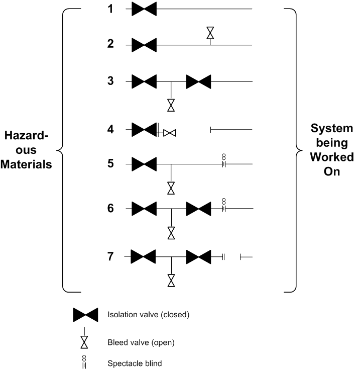
The sketch shows some of the various isolation techniques that can be used to protect workers in the process industries. The process containing toxic or flammable chemicals under pressure is on the left; the open system, where the workers are present, is on the right. The order is from the least to the most secure.

There are many ways of isolating equipment. Each offers different levels of security. They include
- Level 1 — Closed Valve
- Level 2 — Closed Valve with Open Bleeder
- Level 3 — Double Block and Bleed
- Level 4 — Block and Bleed with Line Break
- Level 5 Block, Bleed and Spectacle Blind
- Level 6 Double Block and Bleed with Blind
- Level 7 — Double Block and Bleed with Line Break
Pipe Blinds
Blinds process piping. Blinds - also known as blanks or spades - provide positive isolation between sections of a process. The following guidance is provided to do with the location, installation, and use of blinds.
- At battery limits in all process, utility, relief, and blowdown lines;
- As required for inspection, maintenance, testing, or alternative operation of
equipment, such as vessels, heaters, rotating equipment, or exchangers; - Where segregation of fluids is required;
- Blinds should be installed in horizontal lines where possible. Doing so makes
handling and installation easier and reduces the chances of damaging the
gaskets during installation. Also, blinds in vertical lines may trap liquid above
them. For this reason, blinds should not be used in vertical water or steam
lines where there is a potential for freezing; - Blinds for rotating equipment and the tube side of shell-and-tube heat exchangers should not be located at the equipment flanges;
- Piping at locations where blinds and their associated spool pieces should be arranged so as to permit the removal of the bolting for the blinds, and to allow space for swinging the blind once it is unbolted;
- Supports to maintain piping alignment when blinds are being installed or removed are required if the piping or other items, such as valves, are located at or near the blind location;
- When selecting a location for a blind to be inserted it is important to make sure that sufficient space is available not only to insert the blind but also for the equipment needed to lift the blind into place;
- When it is expected that a blind will be inserted and removed on a regular basis, platforms should be provided;
- Permanent handling equipment shall be provided for all blinds weighing more than 45 kg (100 lb).
Most blinds are either of the line or spectacle type.
A line blind - also known as a spade, paddle, skillet, pancake, or slip blind - consists of a solid metal disk with a thin length of metal attached to it. The metal of the blind should be rated for full process pressure on one side and atmospheric pressure on the other side. The handle on the blind should be long enough so that it can be seen through insulation and any other materials that might be covering the flange.
Spectacle Blinds
If a flange is to be routinely blinded, a spectacle blind (also known as a figure of eight blind, disk and donut, or simply a spec blind) can be installed. This type of blind looks like a pair of spectacles or the number 8, with one section closed and the other open.
When the flange is broken and the line cleared, the blind can be rotated around the one bolt that is left in the flange. It is simple to ensure that the blind has been installed because the open part of the blind will be sticking out from the flange face.
If spectacle blinds in horizontal pipes are insulated, the spectacle blind should point downwards at an angle of 45º to avoid water leaking into the insulation.
Figures 3 and 4 show spec blinds in the open and closed positions respectively.
