Standard Examples

We have developed a set of process safety management standard examples that are used to illustrate some of the concepts and ideas developed in our publications.
Example 1 - Facility Design
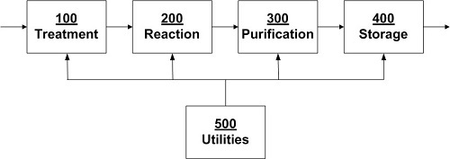
A process consists of four operating units and a utilities section. A schematic of the system is shown in Figure 1.
Example 2 - Process Flow
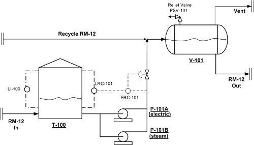
Figure 2 shows part of Unit 100 from Figure 1. Liquid flows into an Atmospheric Tank, T-100. The liquid, which is both flammable and toxic, is called Raw Material Number 12 - abbreviated to RM 12. From T 100, RM 12 is pumped to Pressure Vessel, V 101, using Pump P-101A or P-101B, either of which can handle the full flow (A is normally in service, with B being on standby). The pumps are driven by a steam turbine and an electric motor respectively.
The flow of liquid both into and out of T-100 is continuous. The incoming flow varies according to upstream conditions and is outside the control of the operators responsible for the equipment shown. The flow rate from T-100 to V-101 is controlled by FRC-101, whose set point is cascaded from LRC-101, which measures the level in T-100. The level in T-100 can also be measured with the sight glass, LI-100.
V-101 is protected against over-pressure by safety instrumentation (not shown) that shuts down both P-101 A/B, and by the relief valve, PSV-101.
Failure and repair times for the pumps are provided in Table 1.
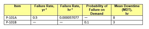
Summarizing Table 1 in words:
- P-101A (which is the pump that is normally in operation) is expected to fail twice a year. It takes eight hours to repair.
- When P-101A stops working, P-101B is started. It is expected that P-101B will fail to start on demand once in ten times. If P-101B does not start immediately its anticipated repair time is three hours.
Example 3 - Heat Exchanger
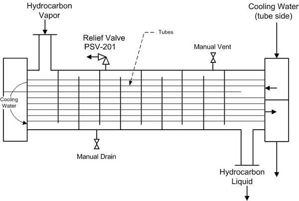
Figure 3 shows a shell and tube heat exchanger. Hydrocarbon vapors enter the exchanger on the shell side where they are condensed by cooling water which runs through two passes of tubes. The pressure relief valve and the drain and vent valves on the shell side are shown.
Example 4 - Risk Management Workflow
The fourth example is used for discussions of the management of risk. Figure 4 illustrates the major steps in the development of a representative risk management program.
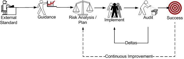
External Standard
The first step in the development of a risk management program is to check for the existence of standards from an external agency - generally either a government regulator or a company's own corporate group). Regulations are broad in scope. Corporate standards are likely to be more specific because they focus on just those operations that the company carries out.
Guidance
Because external standards do not generally provide enough detail to actually develop and run a risk management program additional nuts-and-bolts guidance is needed. Such guidance can be internally generated or it can be provided by outside experts and consultants.
Risk Analysis Plan and Implement
The next step is to conduct a risk analysis that will help determine what risks exist, how those risks can be mitigated, and how resources should be prioritized. Planning is followed by implementation.
Audit / Deltas
No management program is perfect. Gaps between goals and reality always exist. In order to systematically identify the gaps, audits are needed. If the audit finds deficiencies or gaps, the process recycles to the implementation step. (The word "delta" is sometimes used to describe the difference between plan and performance because it sounds less critical than words such as "deficiency" or "failure".)
Success / Continuous Improvement
Ideally, once the plan is implemented and has been audited, management can declare that they have successfully implemented their risk management program. However risk can never be low enough; improvements can always be made. Therefore, once the program has been completed, management should start the whole process over again - usually at the risk analysis and planning steps - in order to achieve even higher levels of safety and economic performance.
Example 5: Significant Potential Incident
This example is loosely based on an actual event that occurred at a process facility. Fortunately the incident did not result in a major loss, but it does provide some opportunities for lessons learned.
A cone-roof, atmospheric storage tank stores a non-flammable, low vapor pressure inorganic liquid. The vapor space above the chemical is air; the tank breathes in and out through a simple vent line. A small, steady stream of the inorganic liquid is pumped from the tank into the process, which contains light hydrocarbons at moderately high pressure. One of the facility's private roads is located close to the tank. A small but steady stream of vehicles uses the road.
On a number of occasions the pump stopped operating, the check valve failed to hold and light hydrocarbons flowed backward from the process into the tank. A layer of hydrocarbons formed on top of the inorganic liquid, as shown in Figure 5. No instrumentation was installed to warn of the occurrence of this event.
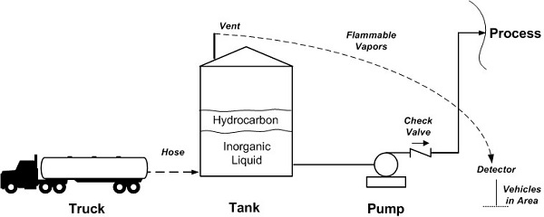
The tank is refilled with the inorganic liquid about once a month from a truck. As the level in the tank rose during the truck unloading process vapors from the hydrocarbon layer came out of the vent. A hydrocarbon detector located about 100 meters from the tank detected the presence of flammable vapors and sounded an alarm.
The incident was a near miss ? the vapors did not light off, and no one was hurt. (There were, however, economic costs associated with cleaning out the tank safely.) However the potential for a serious event was high - the vapors could have ignited at a vehicle engine or exhaust manifold. The flame front could then have entered the tank and caused a large explosion.
Copyright © Ian Sutton. 2023. All Rights Reserved.